Slab
Track

A New Standard for Track Construction
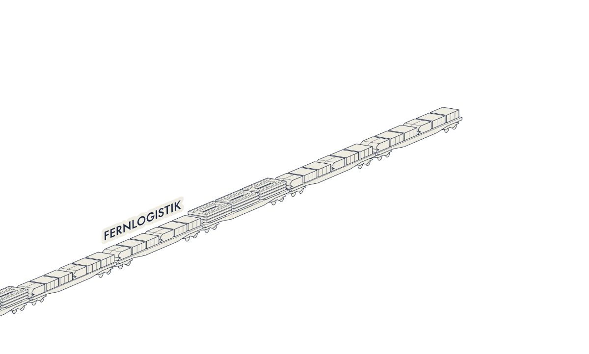
Our logistics and construction method applies industrial principles to railway construction. Its new system logic organizes the flow of materials all the way to the construction front and, through standardized, repeatable processes, creates the conditions for consistently high construction rate — from the first to the last day of the project.
The method demonstrates particularly strong potential under demanding conditions, such as tunnel projects. It can significantly reduce the site footprint alongside the track while also lowering energy consumption, CO₂ emissions, noise and dust.
System Overview

Maximum Efficiency Through System Logic

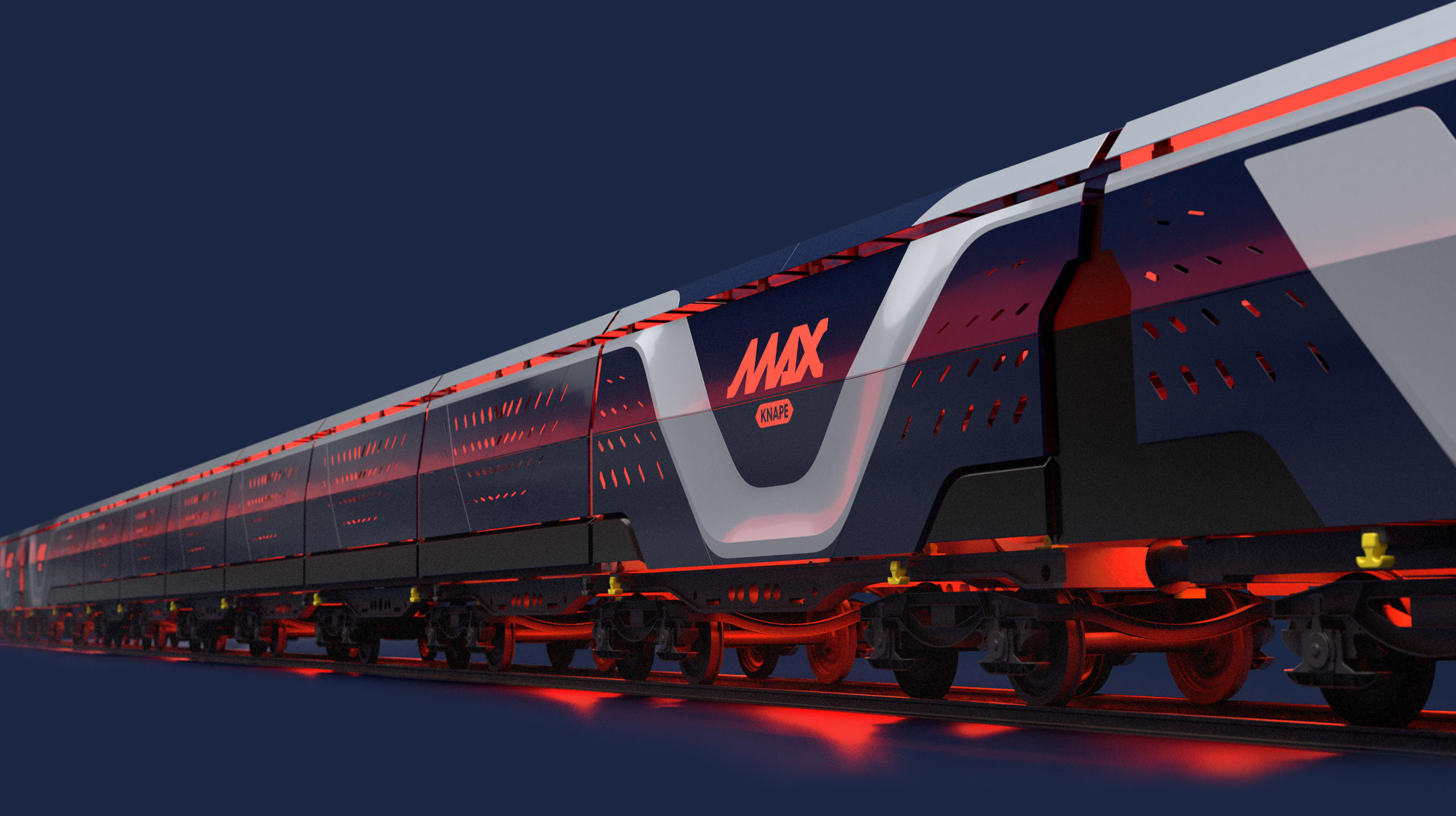
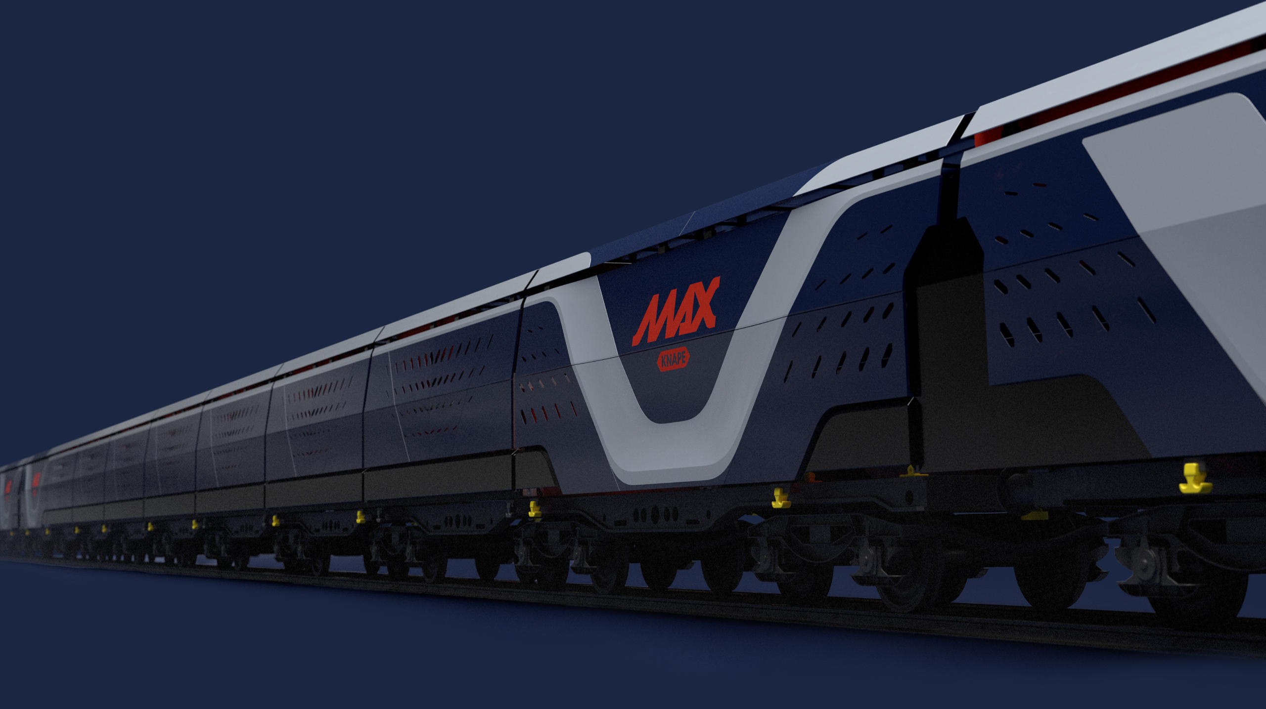
The MAX Knape system seamlessly integrates logistics and construction into four perfectly synchronised, continuously repeating processes: Loading, Transloading, Shuttling and Construction.

This system logic creates the conditions for consistently high construction speed, regardless of the distance between the construction site compound and the active work front. The result is the potential for significantly shorter project durations while reducing the use of resources.

Together, we can assess the potential of the MAX Knape system for your specific construction project.

Loading at the Yard

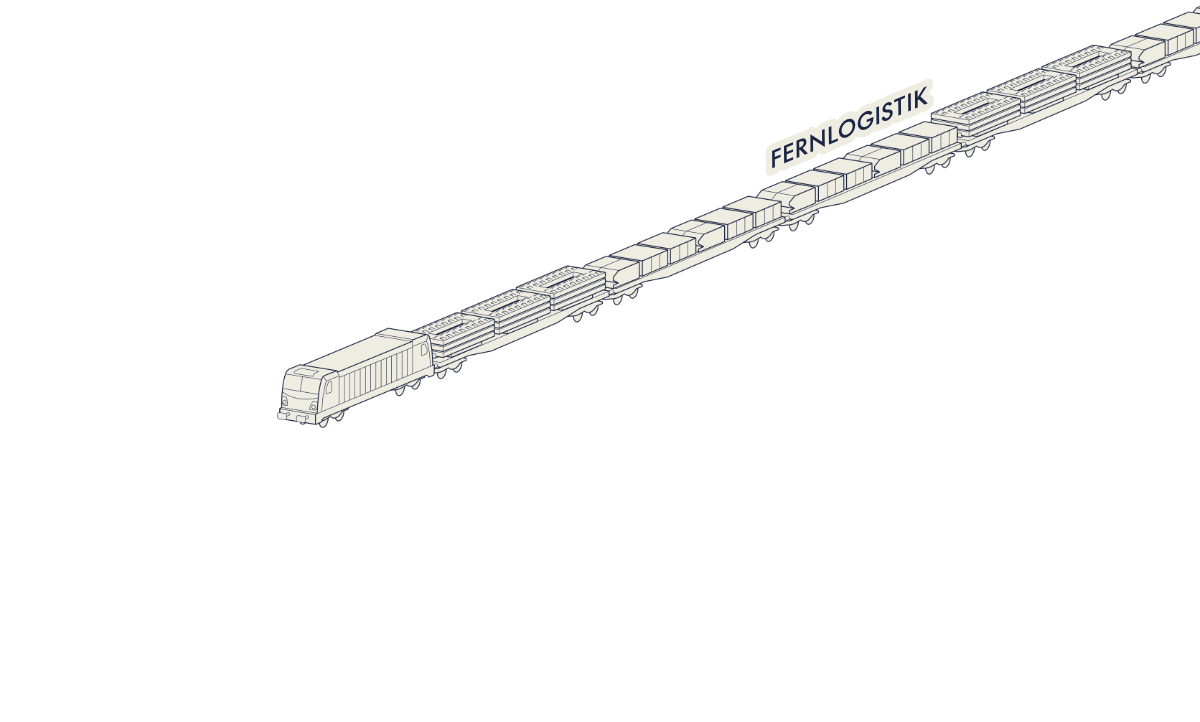
The precise cadence begins at the rail-connected yard — for example, a gravel plant, which can be located more than 100 kilometers away. There, at fixed intervals, the container flatcars are prepared for deployment. The boxes are filled with pre-portioned raw materials for concrete production at the active work front and loaded, along with the slab track plates and rails, via a reach stacker. The material for a full day's output is digitally tracked and transported daily to the transloading point via long-distance logistics.

The illustrations are provided for schematic purposes only. The actual implementation may vary depending on the project. We would be happy to advise you personally.
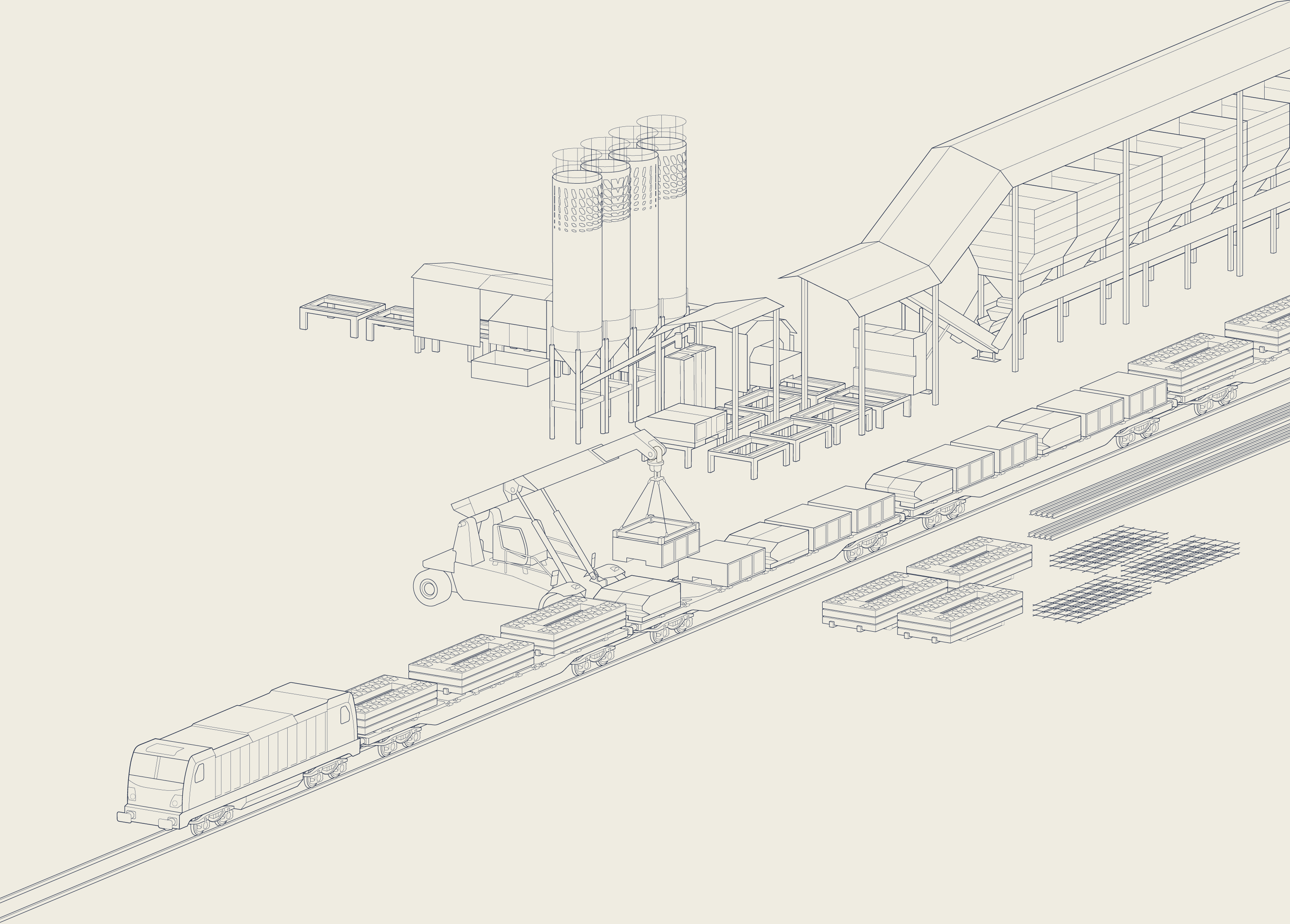
* The illustrations show schematic examples for visualisation purposes. The actual implementation may differ. We would be happy to advise you personally.

Transloading at the Tunnel Portal

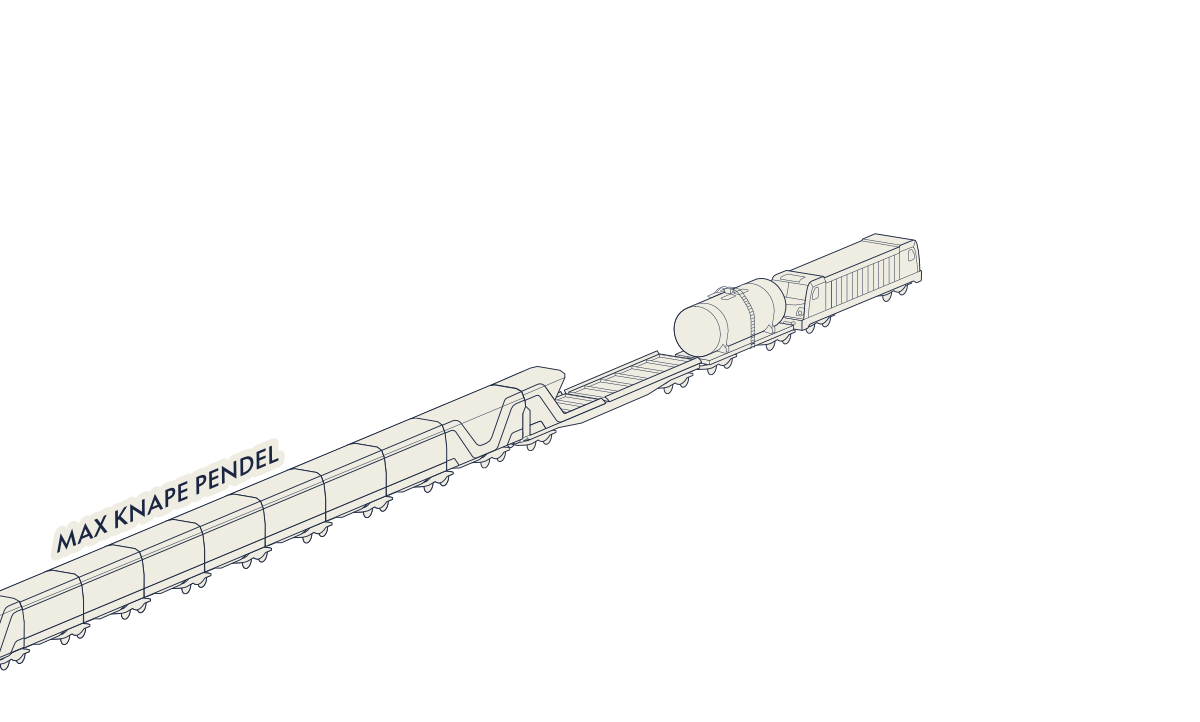
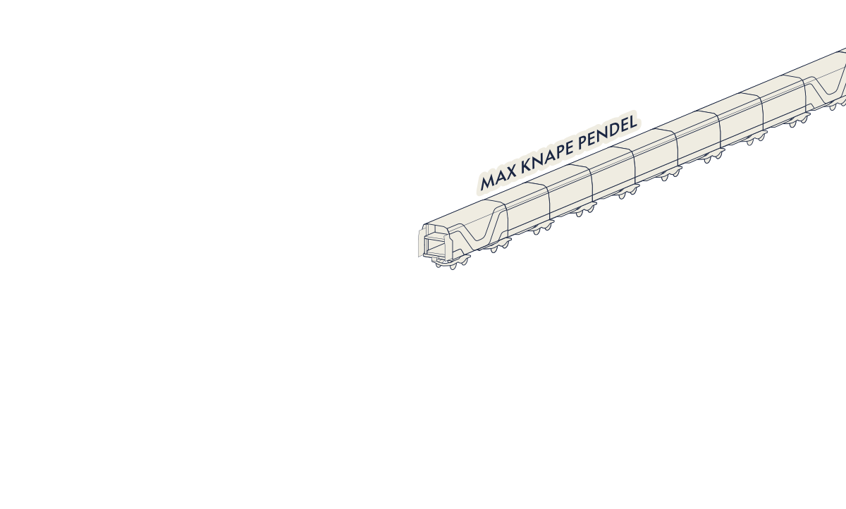
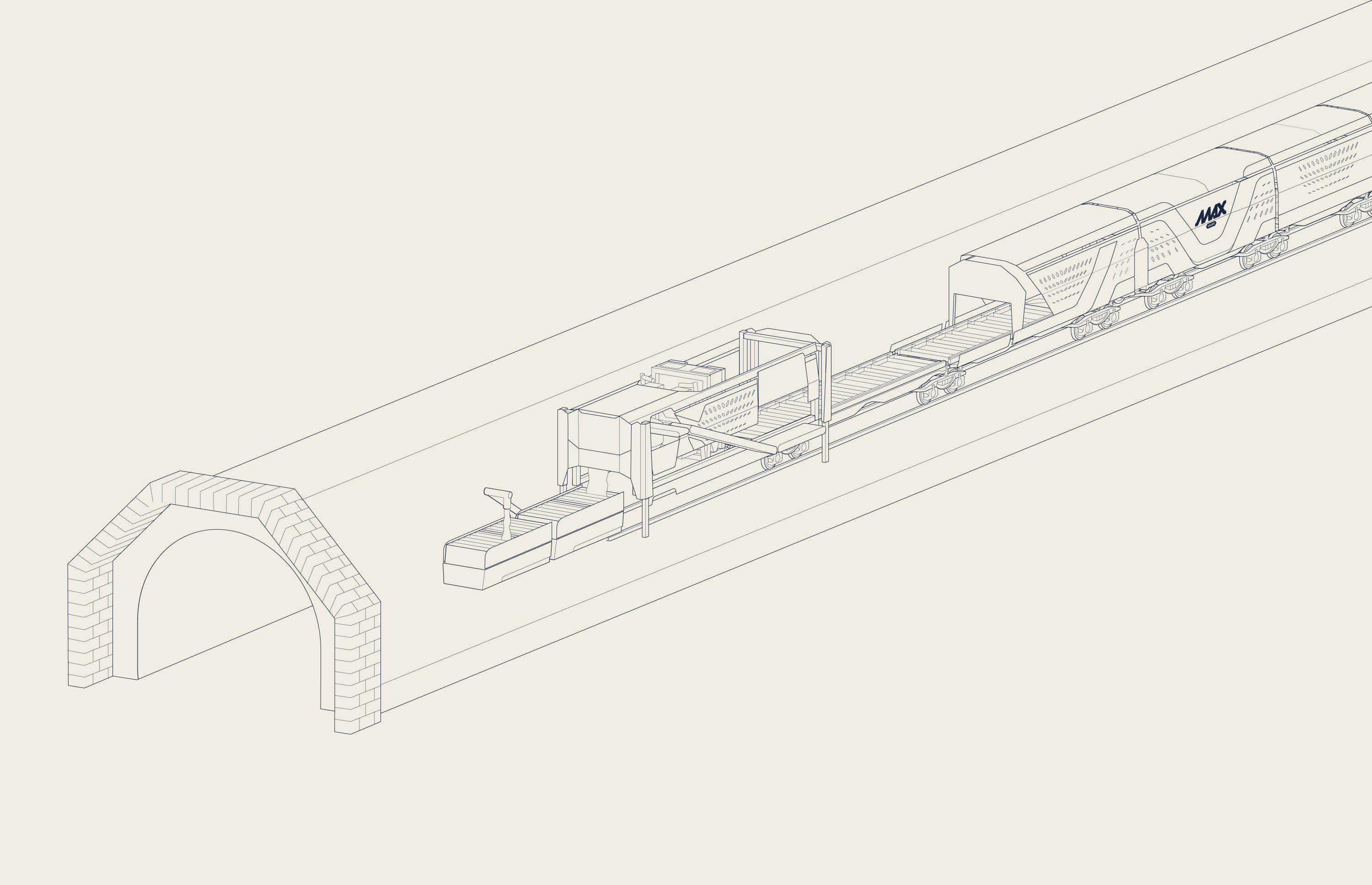
At the transloading point, long-distance logistics meets the MAX Knape system. Here, the material is transferred by crane in just 20 minutes, as often as required daily. While the MAX Knape shuttling system rolls into the tunnel to continuously supply the active work front, the long-distance logistics simultaneously takes empty boxes and used material back to the yard. This direct transfer eliminates the need for a space-intensive staging area at the tunnel portal.

The illustrations are provided for schematic purposes only. The actual implementation may vary depending on the project. We would be happy to advise you personally.
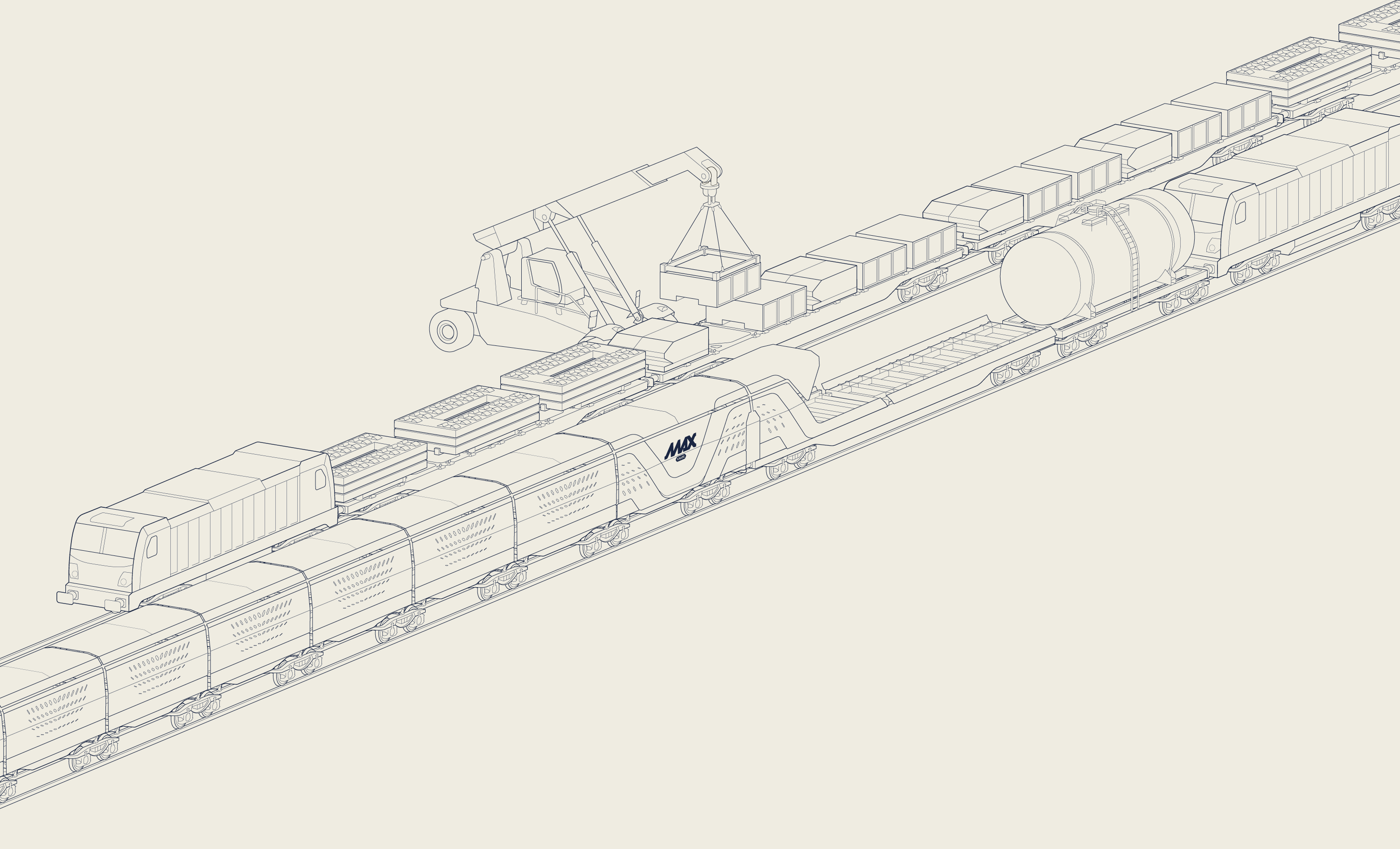
* The illustrations show schematic examples for visualisation purposes. The actual implementation may differ. We would be happy to advise you personally.

Shuttling between Transloading Point and Active Work Front

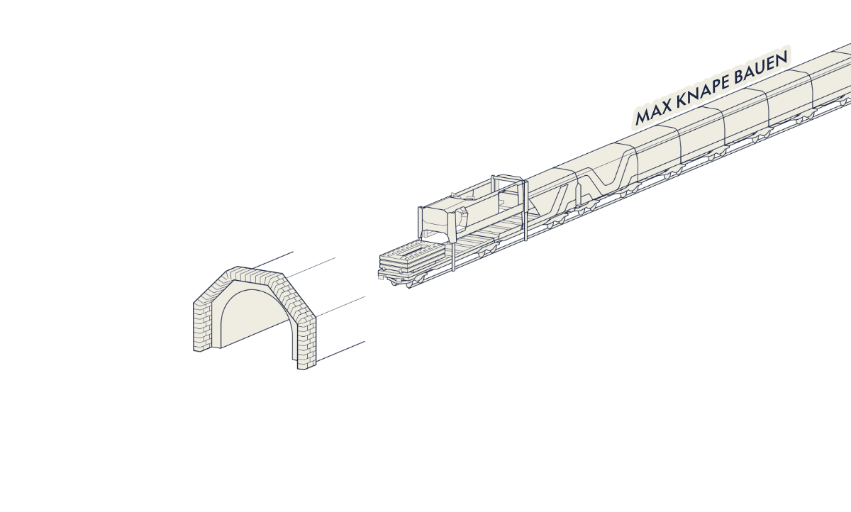
The MAX Knape system consists of two perfectly synchronized components: the construction system at the active work front and the shuttling system that ensures the material flow between the transloading point and the active work front. After coupling, the simultaneous transfer begins: while the construction system on the lower level is fed with new material, used material and empty boxes are concurrently returned to the shuttling system on the upper level. We call this the material exchange.

The illustrations are provided for schematic purposes only. The actual implementation may vary depending on the project. We would be happy to advise you personally.
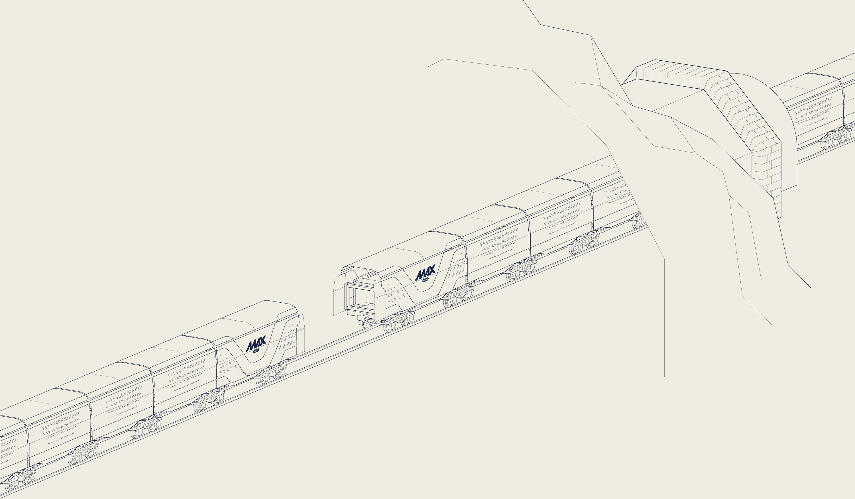
* The illustrations show schematic examples for visualisation purposes. The actual implementation may differ. We would be happy to advise you personally.

Constructing at the Active Work Front

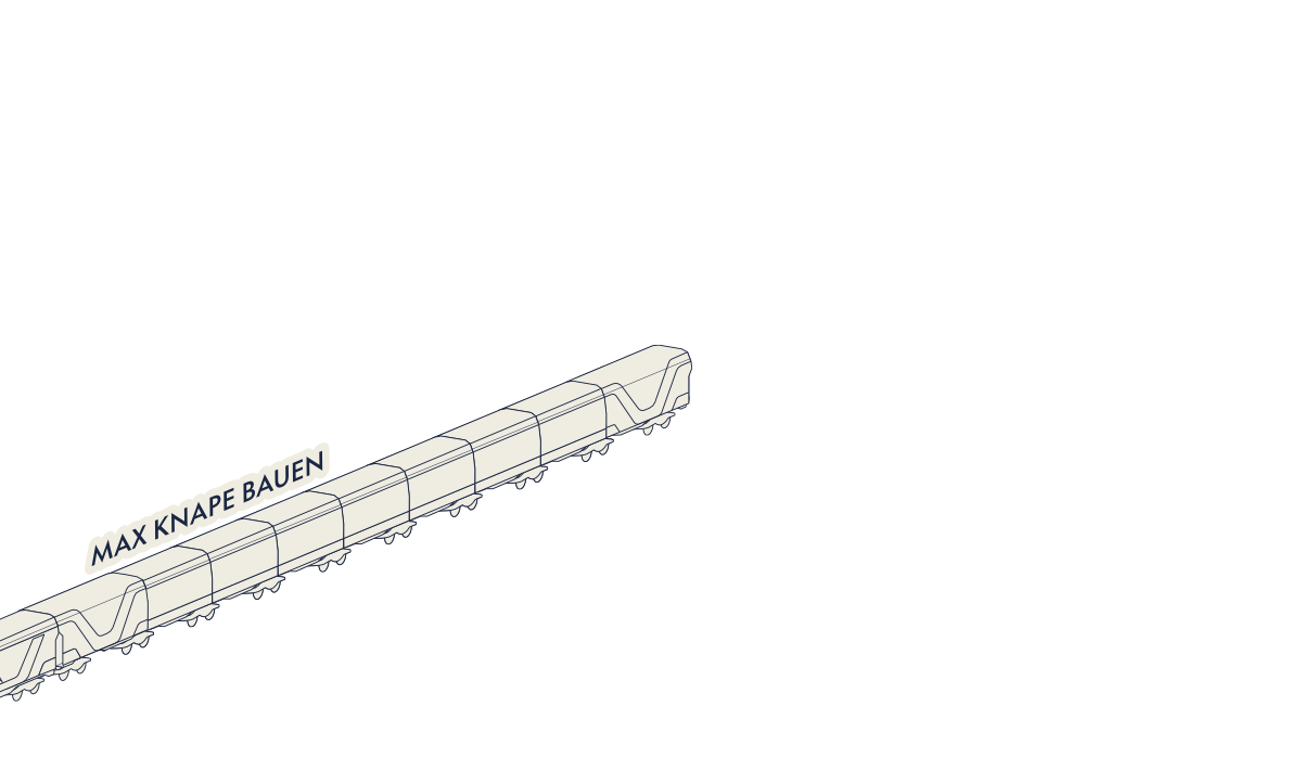
Once the fully loaded shuttling system is unloaded, it travels back to the transloading point. The construction system remains in the tunnel to continue its highly efficient work: First, a gantry crane places the slab track plates (STA) with maximum precision. After lifting and alignment, the rails are set in place. Subsequently, the concrete mixer produces fresh, premium-quality concrete to grout the STA. At the end of the shift, the entire unit is prepared for its next deployment at the transloading point. The centerpiece: the full use of the gantry crane and concrete mixer.

The illustrations are provided for schematic purposes only. The actual implementation may vary depending on the project. We would be happy to advise you personally.
Benefits
Slab Track

More
Speed

Up to 240 m of track installed per working day

Greater
Process Reliability

Through repeatable daily workflows

More
Sustainability

Up to 60 % lower CO₂ emissions

Smaller
Site Footprint

Only around 4,000 m² of site compound area

Higher
Concrete Quality

Daily concrete production at the construction front

More
Quality

Repeatable workflows ensure consistent results

Greater
Efficiency

Achieve more with fewer personnel

Reduced
Transport Routes

No road transport required